2020 - 2021 competiton
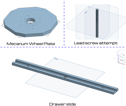
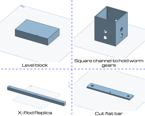
custom created parts in onshape
|
|
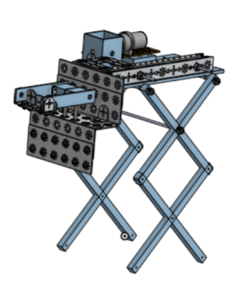
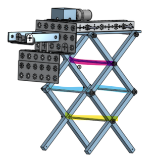
progression of scissor lift
|
This was built over the course of a week by 3 of our builders and put into CAD by me later. (Before the first qualifier)
CAD includes:
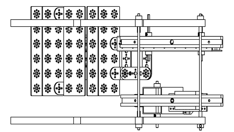
The grabbing mechanism (including the building plates and flat bars) was designed for maximum surface area contact with the block making it easier to hold the block when lifted. The purpose of the axel connecting the two scissor lifts is to improve lifting synchronization and improve balance. |
|
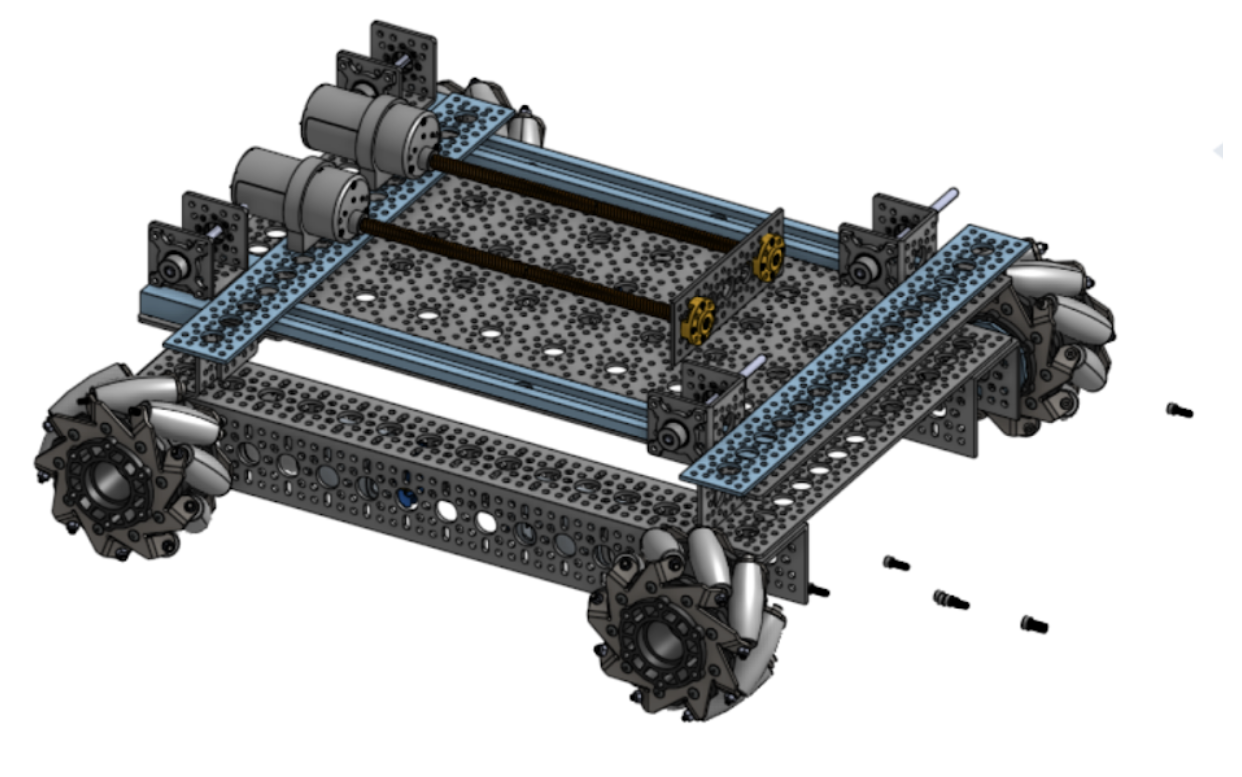
progression of chassis design
|
The chassis was built using Actobotics parts except for the two larger channels on the sides made of GoBuilda parts. This is the basic chassis design that was used during the first qualifier.
NOTICE: We cut the lead screws that we had and I could not figure out how to scale, so the lead screws on the robot are longer than the ones on the ones in the CAD CAD Includes:
|
|
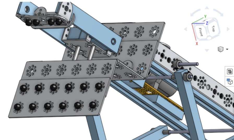
progression of STABILIZATION 1
|
Goal: Stabilize the scissor lift.
Problem: The issue we ran into during our first competition was that the scissor lift was slightly tilted and lifted unevenly. It’s lopsided CAD Solution: Add long axels to connect the two scissor lifts to make the lifting more in sync, stable, and balanced. The axel highlighted in pink is the one that was initially put onto the scissor lift to help connect the two scissor lifts. My idea to make it more stable is to add three more axles. The yellow one would be the best one to start with, and so would the front blue one. (Yellow one was added on 3 Feb 2020). |
|
progression of arm grip
|
Goal: Come up with a way to grip the blocks
Problem: We originally used rubber bands and covered the building plate and top flat bar, however, it was very uneven on the left side and left space between the block and the plate in some places making our grip unreliable. CAD Solution: Use rubber nubs to use as a grip instead and space them out evenly along with both the plate and the top flat bar so that the grip on the blocks will be even no matter where we grab them from. |
|
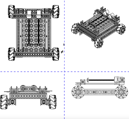
chassis and scissor lift cad drawing
|
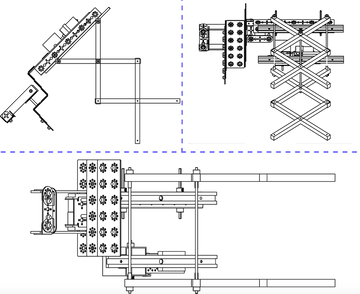
|
|
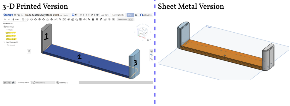
scissor lift cad
The task was to CAD and print a new, single grabber piece.
The goal of this design was to replace the claw part of our grabbing mechanism. Everything is the same size as the original piece, however, the point of printing this print was to have one part instead of the flat bracket and two L brackets on the sides.
The problem we ran into with this piece was that I could not export it because Onshape separated my design into 3 parts instead of 1 (highlighted below). I tried putting the object into Assembly, grouping it, then export it from there, but it was still listed as 3 parts. I found that I can export each part individually, however we would be printing each part individually and that defeats the purpose of a single print CAD design of the grabber.